For this 2 week activity, students will use a Topcon Total Station and GMS-2 GPS unit to survey the campus mall here at UWEC. Earlier in the semester students used a laser rangefinder to conduct a distance azimuth survey in Field Activity #4. Now, students will expand on their knowledge of surveying by including elevation (Z) data in their models.
Study Area
The study area for the survey will be the newly developed campus mall in the middle of UWEC's lower campus. The area is mainly open grass with sidewalks and stone benches throughout. The land has a gentle slope towards a stream that runs through lower campus and elevation data for this survey should not vary by more than a couple feet. Because this area is so newly developed, current aerial imagery is not available. The imagery used in this activity will still have the old Davis Center on top of the new campus mall, but will still be helpful in visualizing the elevation in the middle of lower campus.

Methods
To preform the survey, a Topcon GPT-3100W Total Station was set up and connected to a Topcon GMS-2 GPS unit via Bluetooth. The tripod was opened and stamped into the ground. Then the total station was screwed on top and the tripod was adjusted to a level position by using the bubble level on the base of the total station and at a proper height so that bending over to look through the lens would not be an issue. Once the rough leveling is complete, the leveling process continues by use of the dials on the base of the total station and a larger bubble level above the screen and below the lens of the total station. After the tripod and total station were set up and leveled, Bluetooth was enabled on the total station. The GMS-2 was then turned on, the application Topserv was opened, and a new job was created. The coordinate projection used for this activity was set to NAD 1983 UTM Zone 15N. Once a new job is created, the Bluetooth manager will appear (or can be found in the desktop taskbar) and the appropriate Bluetooth enabled device should be chosen, for this activity GPT(TSS) was chosen.

Figure 1: The tripod. The height is adjusted for each individual leg by manipulation of the black screws near the base of the legs seen in the picture. There are small metal protrusions on the legs for stamping the pointed leg ends down into the ground to ensure stability.

Figure 2: The Topcon GPT-3100W Total Station.

Figure 3: The Topcon GMS-2.
Next the occupy point was taken. The occupy point is taken where the center of the total station is located. This is done by changing the observation mode on the GMS-2 to GPS+ and holding it directly underneath the total station or as close to the middle as possible. In the job menu, choose collect, then choose collect features. Press start and the GMS-2 will collect its position and in effect collect the position of the total station.
Now that the occupy point is taken, a backsight needs to be collected. A backsight is needed in order for the software to know where the total station is located in 3-dimensial space by providing a reference point for the occupy point. To set the backsight, change the observation mode to Total Station, choose collect in the job menu and choose OCC/BS setup. Here the occupy point taken earlier is selected and the height of the total station and the prism rod is entered. Next the total station is directed at the backsight point and aimed into the prism, the azimuth is recorded through use of a compass, and HC Set is chosen to take the backsight.

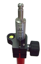
Figure 4: The prism rod and prism. The height of the prism can be adjusted by manipulation of the black dials seen in the picture.

Figure 5: The prism will reflect the laser given off by the total station directly back at itself as long as the laser hits anywhere within the prisms diameter.

Figure 6: There is a small bubble level where the measurements begin on the rod to help keep the prism straight and steady.
Now that the occupy point and backsight are established and all height information is entered, data can be collected. Navigate from the job menu to the collect menu, then collect features. Once the cross heirs on total station are within the prism, choosing meas. at the bottom right corner of the screen will collect the point. The lens of the total station can be focused to better see the prism and crossheirs by use of a dial directly around the viewing lens. There are also two nobs on the total station that can be turned to lock, horizontally and vertically, the total station in place when taking measurements at a great distance.

Figure 7: Eric and I (holding the GMS-2) trying to set up a Bluetooth connection with the total station. Also a picture of our study area, notice the lack of building. This is when we were still having problems and ended up having to try again the next day. The total station in this picture is a little too low for us to use comfortably and was raised up about 2-3 inches the next day we preformed the survey.

Figure 8: Here I am holding the prism rod for our backsight measurement.
In surveying the campus mall, 130 points were taken in a fashion to cover the entire area completely. The GMS-2 was then connected to a computer via USB cable. The data was exported by navigating from the job menu to the export menu and choosing, to file. The text (.txt) file format was chosen to preserve the coordinate and elevation aspects of the points. In ArcMap, the data was imported by choosing File > Add Data > Add X/Y Data... and choosing the text file exported from the GMS-2. A continuous surface and digital elevation model (DEM) was created from the points. More on DEMs can be found in Activity #2.
Results/Discussion

Figure 7: The final elevation model produced from the survey. The building seen in the picture is the old Davis Center and is no longer present today. What is present is an gradual downward slopping open field which is illustrated through the generated surface.
The resulting elevation model shows a gradual decline of elevation from the northeast to the southwest with a range of elevations just over four feet. This is exactly what was expected, a gradual slope of not much variance.
While conducting this survey, Group 3 came across multiple Bluetooth problems with easy solutions.
1. Turn the Bluetooth on the total station first before doing anything with the GMS-2. This will help minimize any Bluetooth connectivity problems later on. This is done by pressing menu on the total station, then f4 twice and f2 to select parameters. Then press f4 twice and f3 to select Bluetooth. Hit f4 one more time and the total station should say Set!
2. After enabling Bluetooth on the total station or changing any settings, always remember to press esc to close out of any menus. The Bluetooth connection will fail if the total station is not on its main screen when data is trying to be collected.
Conclusions
The generated surface made through the survey showcases the real world aspects of elevation for the campus mall very well. The gradual decline in the southwest direction depicted by the model accurately describes the terrain. Conducting this survey was a great learning experience in how to set up and use a total station. It was extremely rewarding to create a model from self collected data and GIS knowledge from past activities.
Picture Credits:
Hai your methods of Total Station surveying the campus mall information very useful for me..I have read this post and if I could I want to suggest you few interesting things or advice.. Right time share with me..Thanks a lot!!!!
ReplyDelete